A Solar Shade at Sun–Earth L1
Executive Summary
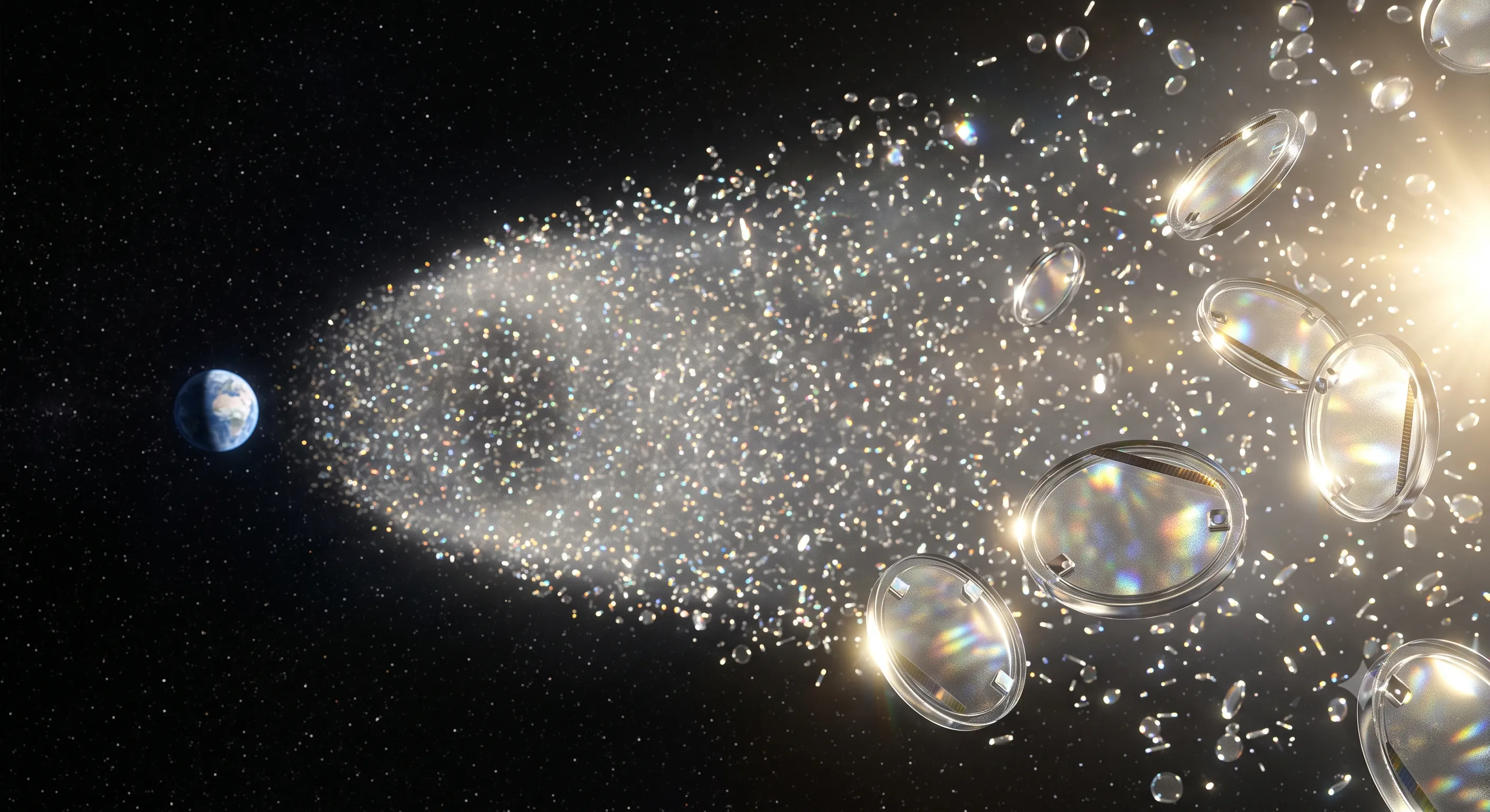
Blocking approximately 2% of incoming sunlight before it reaches Earth could offset a substantial fraction of anthropogenic radiative forcing. This paper outlines a system architecture for doing so: a swarm of roughly 16 trillion small, self-rigid glass-film “flyer” disks stationed near the Sun–Earth L1 Lagrange point, manufactured primarily on the Moon from regolith-derived glass, and launched to L1 by electromagnetic mass driver.
Provenance note. This paper is a synthesis, not an original proposal. The flyer swarm concept, mass budget, and electromagnetic launch approach follow Angel (2006);1 the deflection-rather-than-absorption principle originates with Early (1989);2 the self-replicating lunar factory and closure framework follow the NASA/ASEE Advanced Automation for Space Missions study (Freitas & Gilbreath, eds., 1982);3 and the lunar mass driver concept follows O’Neill (1974) and subsequent work by O’Neill, Kolm, and colleagues.456 Novel contributions here are limited to integration and phasing. Citations are marked throughout.
The central findings:
- Deflection beats absorption. Transparent refractive/diffractive films at ~1 g/m² areal density minimize mass, thermal load, and radiation-pressure station-keeping cost simultaneously.
- Swarms beat monoliths. Trillions of meter-scale disks degrade gracefully under micrometeoroid flux, require no deployment structure, and are manufacturable by wafer-fab-style mass production.
- The Moon beats Earth launch. At ~20 million tonnes total system mass and ~700,000 tonnes/year of sustained throughput, terrestrial launch is the binding constraint. Lunar regolith is ~45% oxygen and ~21% silicon — effectively glass precursor — and a lunar mass driver reduces marginal launch cost to the cost of electricity.
- The project is a flow, not a stock. Attrition requires replenishment of a few percent of the swarm annually, indefinitely. The true deliverable is not a shade but a permanent, largely self-replicating industrial institution.
- Total cost is a few trillion dollars. A bottom-up estimate yields ~$1.5–4 trillion to full deployment and ~$20–60 billion/year thereafter — consistent in magnitude with published Earth-launch estimates,17 but with spending front-loaded into compounding infrastructure and an order-of-magnitude cheaper perpetual steady state.
1. Mission Geometry and Scale
1.1 Location: Sub-L1
The shade must sit between the Sun and Earth, near the Sun–Earth L1 point (~1.5 million km sunward of Earth). Radiation pressure on the shade shifts the effective equilibrium slightly sunward of geometric L1; this displaced equilibrium is itself a design variable coupled to areal density. The use of the sub-L1 region for a climate sunshade was analyzed by Early (1989)2 and McInnes (2002),8 with Angel (2006)1 providing the detailed treatment adopted here (Angel’s baseline targets 1.8% flux reduction; we round to ~2%).
1.2 Required blocking area
- Target: ~2% reduction in total insolation.
- Effective blocking area required: ~4.5–5 million km² (~5 × 10¹² m²), inflated above the naive 2%-of-Earth’s-disk figure by penumbral leakage at L1 distance and imperfect deflection efficiency.
1.3 System mass
At ~1 g/m² achievable areal density (film + electronics + control tabs), total system mass is on the order of 20 million tonnes.
2. Flyer Design
2.1 Optical strategy: deflect, don’t absorb
This principle is due to Early (1989),2 who first proposed a transparent deflecting shield to minimize radiation-pressure displacement from L1; Angel (2006)1 developed the low-reflectivity refractive screen adopted here.
The shade does not need to absorb or reflect light — only to prevent it from reaching Earth. Deflecting rays by a few arcminutes suffices. Benefits over an opaque absorber or reflector:
- ~10× lower radiation pressure (permits closer-to-L1 station and less control authority)
- Near-zero absorbed heat (no thermal management mass)
- Thinner, lighter films
2.2 Material: engineered glass/ceramic film
- Baseline: transparent film ~1–4 µm thick with a slightly prismatic or perforated refractive surface; Angel (2006)1 proposed silicon nitride.
- Lunar-compatible variant: fused silica derived from regolith — the key enabler of off-Earth manufacturing. Sunshade construction from lunar/space resources was proposed by Jehle, Scott & Centers (2020).9
- Advanced option: diffractive gratings — cf. the NASA NIAC Diffractive Solar Sailing project (Swartzlander, Phase I/II, 2018–2019; Dubill, Phase III, 2022)1011 — potentially below 1 g/m²; wavelength dispersion is acceptable since light merely needs to miss Earth.
- Rejected options: aluminized polymer sails (too heavy, high radiation pressure); graphene (no area-scale manufacturing path, weak optical interaction).
2.3 Unit geometry: small self-rigid disk
The autonomous flyer architecture in this section — self-rigid meter-scale disk, gram-scale avionics, and reflective-tab station-keeping — is Angel’s (2006)1 design, adopted essentially unchanged apart from the edge treatment.
- Diameter ~0.5–1 m; at this scale the film is self-supporting — no booms, masts, or tensioning structure, eliminating the structural mass that typically dominates sail designs.
- Gram-scale avionics: MEMS sun sensor, minimal processor/radio, thin-film solar cell strip printed on the film.
- Attitude and station-keeping: three small MEMS-actuated tiltable mirror tabs at the rim modulate radiation pressure differentially. No propellant, ever. Passive attitude stability via center-of-mass offset sunward of center of pressure.
- Edge treatment: laser-fused or thickened rim (~few % mass penalty) to arrest crack propagation, ensuring micrometeoroid punctures remain punctures rather than tears.
2.4 Micrometeoroid philosophy: accept damage
No armor. Redundancy through numbers: puncture losses across trillions of units shave fractions of a percent of area per decade. A monolithic shade fails catastrophically; a swarm degrades gracefully. Design life per disk: ~50 years.
2.5 Fleet size
The fleet count (~16 trillion), unit mass, ~20 Mt total, and multi-decade deployment schedule below are Angel’s (2006)1 published figures.
| Parameter | Value |
|---|---|
| Effective area required | ~5 × 10¹² m² |
| Area per disk | ~0.3 m² |
| Fleet size | ~16 trillion disks |
| Unit mass | ~1.2 g |
| Total mass | ~20 Mt |
| Production rate (30-yr deployment) | ~500 B–1 T disks/yr (~20,000–30,000/s) |
| Steady-state replenishment | few % of fleet per year, indefinitely |
For calibration: global aluminum can production is ~600 billion units/year. The required rate is factory-scale, not miracle-scale.
2.6 Deployment and swarm architecture
- Disks stack flat like wafers; millions per canister.
- Carrier/tug ejects disks continuously (spring/electromagnetic, slight spin for stability).
- Swarm dispersed into an elongated cloud along the Sun–Earth line (Angel’s baseline):1 negligible collision rates, distributed control. Optimal swarm configurations near L1 are analyzed by Sánchez & McInnes (2015).12
- Each disk self-orients, then trims to its assigned slot over weeks using tab control.
- Governance feature: halting replenishment causes the effect to fade over decades — an inherent off-switch.
3. Manufacturing Architecture
3.1 Why space manufacturing is unavoidable
Sustained throughput of ~700,000 tonnes/year to L1 exceeds any plausible terrestrial launch capacity at acceptable cost. The gravity-well tax must be eliminated for the dumb mass. (For a contrasting view, Fuglesang & García de Herreros Miciano (2021)7 argue an Earth-manufactured, Earth-launched sunshade is the more realistic near-term path; this paper takes the opposite position because of the sustained replenishment requirement.)
3.2 The closure principle: dumb mass from the Moon, vitamins from Earth
The closure concept, the partially-closed factory with Earth-supplied components, and the self-replicating lunar factory architecture in this and the following subsection derive from the 1980 NASA/ASEE study Advanced Automation for Space Missions (Freitas & Gilbreath, eds., 1982),3 particularly its Chapter 5, “Replicating Systems Concepts: Self-Replicating Lunar Factory and Demonstration.”
- Mass closure: fraction of factory output mass producible from local resources. Target: 90–95%.
- Vitamins (Earth-supplied): chips, MEMS, catalysts, precision components — information-dense, grams per kilogram of output. A single heavy-lift launch can carry the electronic payloads for a year of disk production.
- The disk design cooperates: ~99% glass by mass; milligrams of electronics per unit.
3.3 Why the Moon over asteroids
| Factor | Moon | Asteroids |
|---|---|---|
| Feedstock | Regolith ~45% O, ~21% Si — glass precursor | Metals, volatiles |
| Teleoperation latency | 2.5 s (human-puppeteerable) | Minutes (autonomy required) |
| Power | Continuous solar at polar ridges | Variable |
| Launch to L1 | Mass driver, 2.4 km/s, no atmosphere | Long transfers |
Asteroid nickel-iron and volatiles enter as a Phase-5 supplement, not the backbone.
3.4 Seed factory and compounding
- Seed (hundreds of tonnes, Earth-launched): solar furnace, regolith movers, teleoperated assembly robots, pilot glass line, mass-driver starter kit.
- Compounding: all early output reinvested in capacity — collectors, furnaces, robots, rails. With a ~2-year doubling time, one seed becomes ~1,000× capacity in 20 years. The doubling time is the plan’s most sensitive unknown.
- Production: roll-to-roll / sheet fabrication of identical disks with printed electronics — the only manufacturing style humanity has scaled to trillions of units.
3.5 Known failure modes
- Real closure always underperforms paper studies; the last 5% of components (vacuum-rated motors, bearings) hides most of the difficulty.
- Lunar dust degradation of mechanisms.
- Maintenance overhead flattening the compounding exponential.
Near-term de-risking program: kg-scale regolith-to-glass-film demonstration; a machine assembling a copy of its crudest subsystem; empirical closure measurement.
4. Lunar Siting
4.1 Split architecture
Requirements — near-continuous power, water, flat terrain, and a tens-of-kilometers launch corridor — cannot be met at one site.
Seed base: Shackleton–de Gerlache ridge (south pole).
- Sunlight ~80–90% of the year; ice in adjacent permanently shadowed craters; synergy with Artemis infrastructure; continuous Earth comms for teleoperation.
- Long-term role: propellant/water depot, human habitat, R&D annex.
Production complex: southern Oceanus Procellarum (nearside equatorial mare).
- Vast flat basalt plains for a 50+ km mass-driver corridor and factory sprawl.
- Ilmenite-rich regolith (iron, titanium, oxygen).
- Nearside: Earth permanently overhead for teleoperation and vitamin deliveries.
- Equatorial plane within ~1.5° of the ecliptic: favorable launch geometry toward L1 across the lunar month.
- Night-survival power: overbuilt thin-film solar (same production line as the disks) plus molten-regolith thermal storage.
4.2 Mass driver
The lunar mass driver was proposed by O’Neill (1974)4 and developed through the 1977 NASA Ames Summer Study “Mass Drivers I–III” papers (O’Neill, Kolm, et al.)5 and later engineering work (Kolm & Snow, 1992),6 including equatorial-mare siting assumptions. Angel (2006)1 independently proposed Earth-based electromagnetic launch for the sunshade at ~$50/kg; the lunar-driver variant here merges the two lineages.
- Tens of kilometers of straight, level track; gentle acceleration to protect stacked disk canisters.
- Escape velocity 2.4 km/s; no atmosphere; marginal launch cost approaches electricity cost.
- Track oriented for L1 transfer windows and downrange safety; lunar rotational velocity (~4.6 m/s at the equator) is negligible.
- Solar-electric tug fleet (built on-site) performs L1 capture and swarm dispersal.
5. Program Phases
Phase 0 — Survey & proving (years 0–5). Robotic prospecting (polar ice, mare ilmenite). Terrestrial demos: regolith-to-glass, vacuum mechanisms, closure experiments. No large commitment until doubling-time math has empirical grounding.
Phase 1 — Seed base at the pole (years 5–12). Hundreds of tonnes landed; 95% robotic, Earth-teleoperated; human sorties for repair. All output reinvested in power and capacity. Vitamin imports flat while capacity compounds.
Phase 2 — Equatorial expansion (years 10–18). Second-generation seed established in southern Procellarum. Driver corridor graded; first square kilometers of solar farm and thermal batteries; polar base pivots to depot/habitat role.
Phase 3 — Fab and driver commissioning (years 15–25). City-district-scale glass fab: regolith in, disks out at tens of thousands per hour. Driver commissions from test mass to live canisters. First partial shade deployments; cooling begins decades before full effect.
Phase 4 — Steady state (years 25–60+). ~700,000 t/yr launched; swarm grows toward 16 trillion units; radiative forcing curve visibly bends. Self-maintaining complex; a few hundred humans as the maintenance cadre. This phase never ends — replenishment is perpetual.
Phase 5 — The industrial dividend (year 40+). The same production line and driver serve solar power satellites, radiation shielding, telescope starshades, depots, and general cislunar structural mass. Asteroid metals supplement components glass cannot supply. The shade’s sunk cost becomes everyone else’s marginal cost.
6. Cost Estimate
6.1 Literature anchors
Two published estimates bracket the problem. Angel (2006)1 budgeted his Earth-launch architecture at under $5 trillion total — roughly $1 trillion each for flyer production and transportation (both at a $50/kg target), plus development and operations — averaging ~$100 billion/year over a 50-year system life, about 0.2% of world GDP. Fuglesang & García de Herreros Miciano (2021)7 estimate $5–10 trillion for a solar-sail sunshade offsetting ~1°C, also assuming $50/kg launch, with ~$100 billion/year in ongoing replacement. “A few trillion dollars” is thus the consensus order of magnitude for any full-scale sunshade.
6.2 Bottom-up estimate for the lunar-manufacturing architecture
| Cost element | Estimate (2026 USD) |
|---|---|
| Phase 0 — R&D, closure demonstrations, prospecting | $50–150B |
| Phase 1 — Seed base (~500 t landed, hardware development) | $150–500B |
| Phase 2–3 — Equatorial complex, fab, ~60 km mass driver, tug fleet | $300B–1T |
| Vitamin flow + Earth launch during deployment (25–30 yr) | $500B–1.5T |
| Operations, swarm control, ground segment | $200–500B |
| Program total to full 2% shade | ~$1.5–4T |
| Steady-state replenishment (perpetual) | ~$20–60B/yr |
Key drivers behind these figures:
- Vitamin logistics dominate recurring cost. At ~0.5% of disk mass, Earth-manufactured electronics total roughly 100,000 tonnes over the deployment. The cost per kilogram of lunar surface delivery is the single most sensitive parameter in the model; the range above spans roughly $10k/kg (near-term) to a few $k/kg (mature heavy-lift).
- Energy is nearly free at steady state. Launch kinetic energy for 700,000 t/yr at 2.4 km/s is only ~600 GWh/yr, and fab power comes from solar collectors made on the same production line.
- Compounding suppresses marginal cost. Because the factory largely builds itself from regolith, infrastructure capex is front-loaded and the marginal cost per tonne delivered to L1 collapses once the driver operates.
6.3 Comparison with the Earth-launch alternative
Totals are similar; the shape of spending differs. The Earth-launch architecture17 spends continuously on launch with predictable unit costs but a hard affordability floor — replenishment stays near $100B/yr forever. The lunar architecture front-loads risk into infrastructure whose performance (closure fraction, capacity doubling time) is currently unmeasured — a genuine 2–5× cost uncertainty — but rewards success with an order-of-magnitude cheaper steady state. Given that the replenishment phase is perpetual (Section 5, Phase 4), the lunar route’s asymptotics dominate over century timescales.
6.4 Affordability context
Even at the $4 trillion upper bound over 30 years (~$130B/yr), the program is under ~0.15% of global GDP, a small fraction of annual worldwide energy-transition investment, and modest against projected climate-damage costs. The binding constraint is not the sum but the commitment structure: a multi-decade, multi-national, non-lapsing funding obligation — reinforcing the institutional argument of Section 7.
Caveats. All figures are order-of-magnitude. The estimate assumes no cost growth from the historical norm for megaprojects (a generous assumption), excludes governance and liability costs, and inherits the full uncertainty of the closure and doubling-time parameters flagged in Section 3.5.
7. The Master Trade and the Institutional Challenge
The entire design space collapses to one coupling: areal density links equilibrium position, radiation pressure, meteoroid tolerance, unit geometry, and total mass. The transparent ~1 g/m² self-rigid disk is the point where all five constraints relax together, and the swarm architecture is what makes mass, damage tolerance, manufacturing, deployment, and maintenance simultaneously tractable.
The harder half of the problem is not engineering. A perpetual-replenishment system demands an institution — funding, governance, and legitimacy — durable over centuries. The built-in decay of the swarm is both a safeguard (a natural off-switch) and a burden (a commitment that cannot lapse). Any serious program must treat institutional design as a first-class engineering discipline alongside the glass, the robots, and the rail.
References
This whitepaper is a conceptual synthesis of prior published work for discussion purposes; all quantities, including cost figures, are order-of-magnitude estimates. Where design elements are adopted from the literature they are credited inline; errors of integration are the authors’ own.
Footnotes
-
Angel, R., “Feasibility of cooling the Earth with a cloud of small spacecraft near the inner Lagrange point (L1),” Proceedings of the National Academy of Sciences, 2006. https://doi.org/10.1073/pnas.0608163103 ↩ ↩2 ↩3 ↩4 ↩5 ↩6 ↩7 ↩8 ↩9 ↩10 ↩11
-
Early, J. T., “Space-based solar shield to offset greenhouse effect,” Journal of the British Interplanetary Society, 1989. ↩ ↩2 ↩3
-
Freitas, R. A., Jr. & Gilbreath, W. P. (Eds.), Advanced Automation for Space Missions, Proceedings of the 1980 NASA/ASEE Summer Study, University of Santa Clara, NASA Conference Publication 2255, 1982. See esp. Ch. 5, “Replicating Systems Concepts: Self-Replicating Lunar Factory and Demonstration.” ↩ ↩2
-
O’Neill, G. K., “The Colonization of Space,” Physics Today, 1974. ↩ ↩2
-
Arnold, W. H., Bowen, S., Fine, K., Kaplan, D., Kolm, M., Kolm, H., Newman, J., O’Neill, G. K. & Snow, W. R., “Mass Drivers I: Electrical Design” (and companion papers II–III), in Space Resources and Space Settlements, NASA SP-428, 1979. ↩ ↩2
-
Kolm, H. H. & Snow, W. R., “Electromagnetic Launch of Lunar Material,” in Space Resources, Vol. 2, Washington, DC: U.S. Government Printing Office, 1992. ↩ ↩2
-
Fuglesang, C. & García de Herreros Miciano, M., “Realistic sunshade system at L1 for global temperature control,” Acta Astronautica, 2021. ↩ ↩2 ↩3 ↩4
-
McInnes, C. R., “Minimum mass solar shield for terrestrial climate control,” Journal of the British Interplanetary Society, 2002. ↩
-
Jehle, A., Scott, E. & Centers, R., “A Planetary Sunshade Built From Space Resources,” AIAA ASCEND 2020, 2020. https://doi.org/10.2514/6.2020-4077 ↩
-
Dubill, A. L. & Swartzlander, G. A., Jr., “Circumnavigating the sun with diffractive solar sails,” Acta Astronautica, 2021. ↩
-
NASA, “Diffractive Solar Sailing,” NIAC Phase III award (PI: A. Dubill, JHU/APL; Phase I/II PI: G. Swartzlander, RIT, 2018–2019), NASA Innovative Advanced Concepts program, 2022. ↩
-
Sánchez, J.-P. & McInnes, C. R., “Optimal Sunshade Configurations for Space-Based Geoengineering near the Sun-Earth L1 Point,” PLoS ONE, 2015. https://doi.org/10.1371/journal.pone.0136648 ↩
This article represents my personal opinions and research. Nothing in this article should be taken as professional, financial, legal, or investment advice.